Introduction
Ever since the advent of transatlantic flight in the 1940s, aerospace engineers have continually endeavoured to cover the 5000 kilometers in as little time as possible. While modern commercial airliners need over seven and a half hours to traverse this distance, an aircraft that can travel faster than the speed of sound can do so in about two! It however, takes a lot of creative engineering to design something that travels at such a high speed. Team Aero Sapiens, a team of six aerospace engineering undergraduates from IIT Kharagpur, guided by their faculty advisor Prof. Chetan Kumar have tackled this challenge and designed Jatayu- a jet engine to power such a beast.
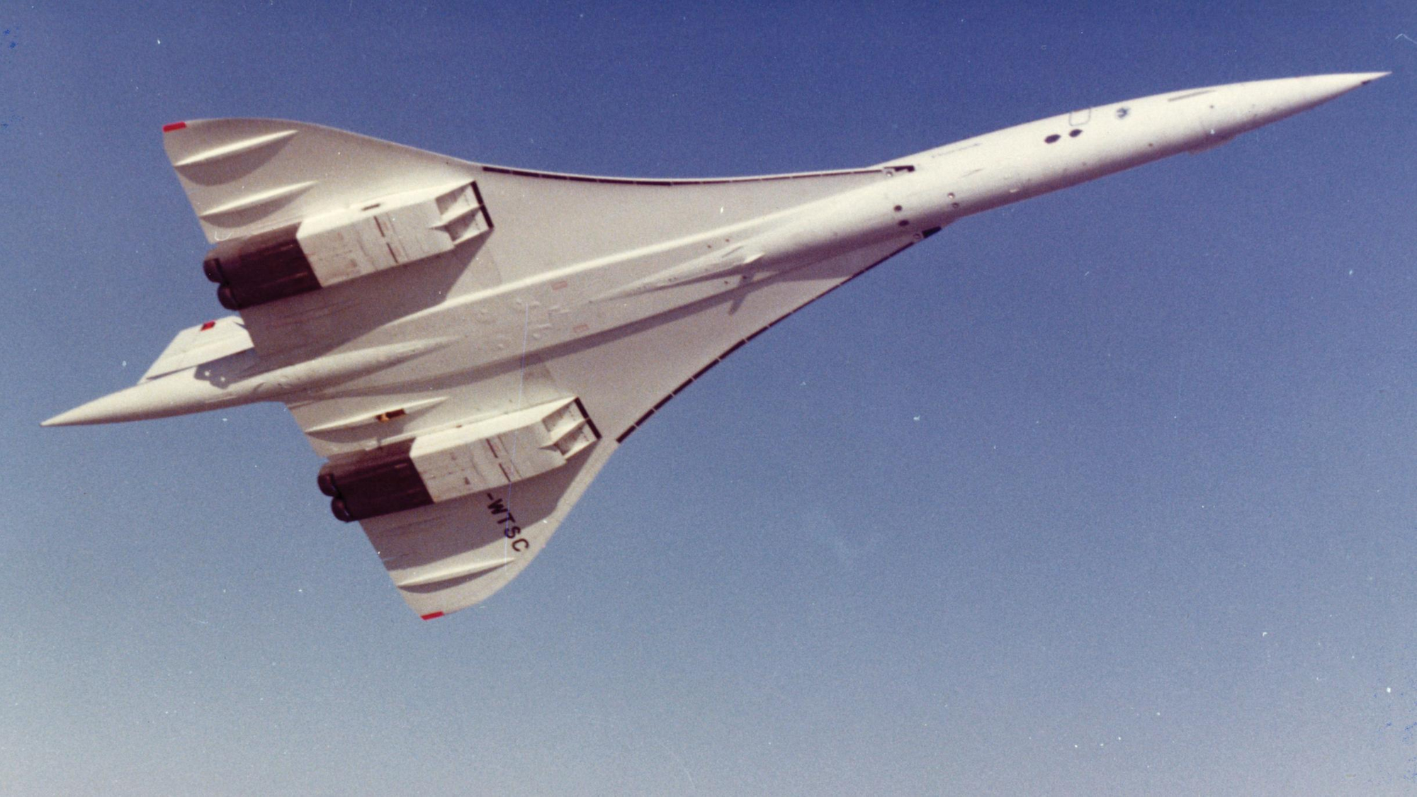
The first and most famous aircraft to ferry passengers across the Atlantic at supersonic speeds was the Concorde, an aircraft developed in unison by Britain and France. It made its debut flight in 1976. Despite being admired as a marvel of engineering, it was put out of service in 2003 following quite a few accidents, high costs of operation and its generation of large amounts of noise. While designing the engine to propel something that had to accomplish the same feat, the team had to keep these issues in mind. The team also had to optimise it to use less than 96000 pounds of fuel and ensure that it was durable and easy to manufacture.
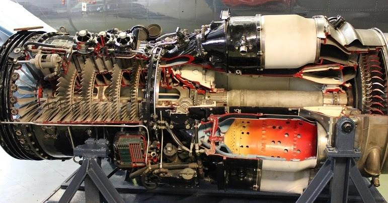
A jet engine works by compressing air that enters it, injecting fuel into the compressed air and then igniting it. The air under pressure, along with the extra gases produced by the combustion of the fuel exit the engine from the rear at a very high speed, propelling the aircraft forward, due to Newton’s third law. The compression is achieved using an elaborate arrangement of compressor fans, both stationary and rotating ones to ‘pack’ as much air as possible into a combustion chamber.
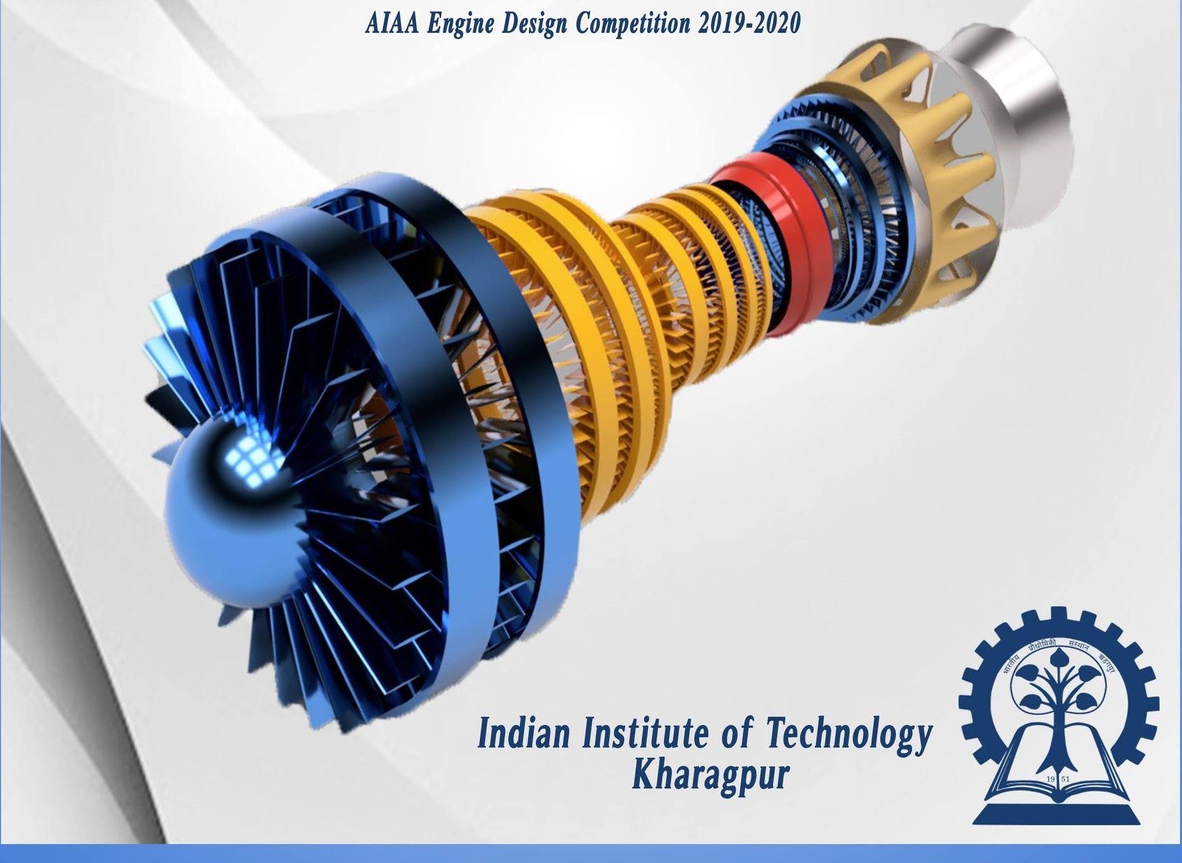
For the competition, the team was provided with the design of a ‘baseline engine’ by the organisers- one that had to be modified and optimised to give the final result. After an extensive literature survey of existing engines and a lot of iteration on Gasturb 13- a simulation software, the team settled on some design choices which led to their design being considerably better than the baseline. A lot of thought and innovation had gone into meticulously designing each subsystem of the engine and integrating them to work in harmony. The sheer ingenuity and cleverness of team Aero Sapiens is reflected in every part of the machine.
The Inlet
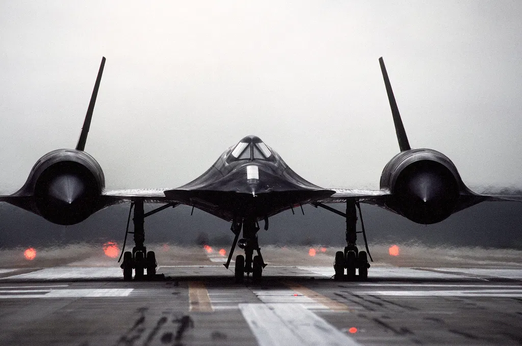
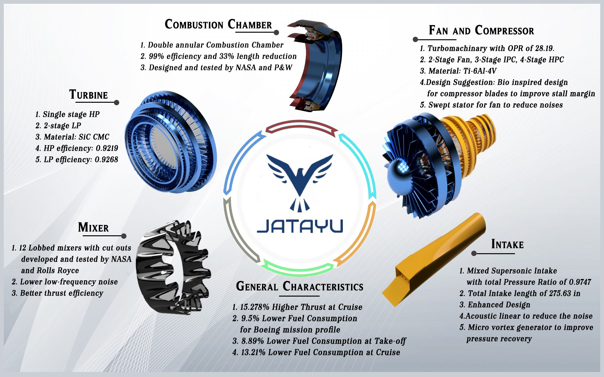
The air intake is the part of the engine where air enters it. It is situated at the very front of the engine. While the design of the air intake of an aircraft that does not travel faster than sound is relatively simple, the design of a supersonic inlet poses a challenge- the air passing through the inlet must be slowed down to a speed less than that of sound so as to avoid damage to the compressors and to facilitate the combustion process.
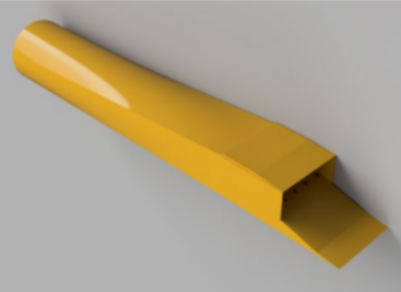
This may be achieved by two main methods- either by having a ‘spike’ in the center of the inlet, a feature seen in many military aircraft, or by having a ‘ramp’ inlet- one which uses variations in its cross sectional area to create shock waves that slow down the air. Aero Sapiens favoured the latter, owing to it being safer and easier to design.
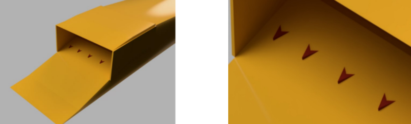
While a ramp inlet is fairly common in supersonic aircraft, there is a problem posed by it- a non-alignment of the stream of air with the centerline of the inlet may cause a region where the air travels with lower momentum than desired. The team mitigated this issue by introducing Micro Vortex Generators (MVGs) in the mouth of the inlet. MVGs are tiny projections on the interior of the inlet, which ‘disturb’ the airflow, causing them to swirl in the form of vortices. This swirling of air enables the low momentum and high momentum air to mix effectively, thus increasing the efficiency of the engine.

The Compressor
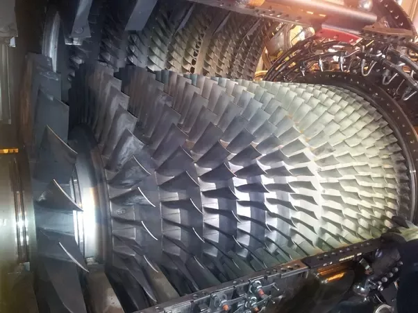
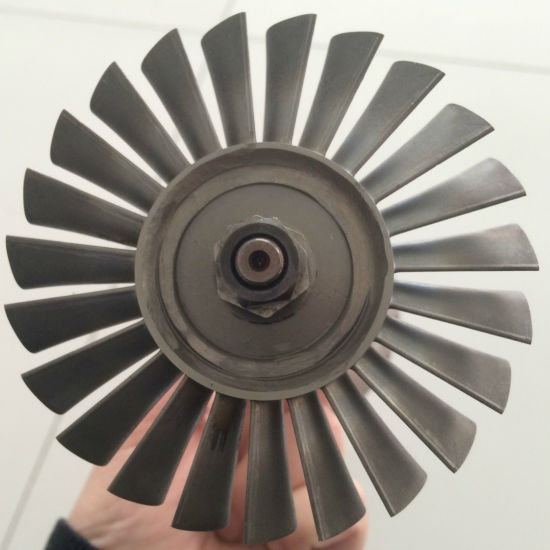
Following its entry into the engine from the inlet, the air flows into the compressor- an elaborate arrangement of blades, some rotating and some stationary, designed to compress the air prior to its ignition in the combustion chamber. This is done so as to maximise the pressure with which the air leaves the engine after combustion, which would, in turn maximise the thrust produced. The compressor works in many stages, each compressing air to a higher pressure than the last. This ensures that the air is ‘packed tightly’ in the combustion chamber, without there being undue stress on one set of blades. There were many innovations by the team in this area.
Aero sapiens succeeded in reducing the number of compressor stages in the compressor from seven in the baseline engine to just four! They did this to achieve a decrease in weight. With an extensive structural analysis of the blades, they selected appropriate materials to lend them strength. Furthermore, because engine noise is an important thing to minimise, especially in supersonic engines, the team intelligently modified the shape of the stators- the stationary fan blades, to produce considerably less noise.
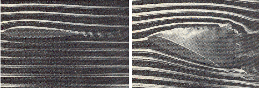
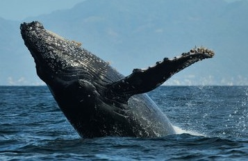
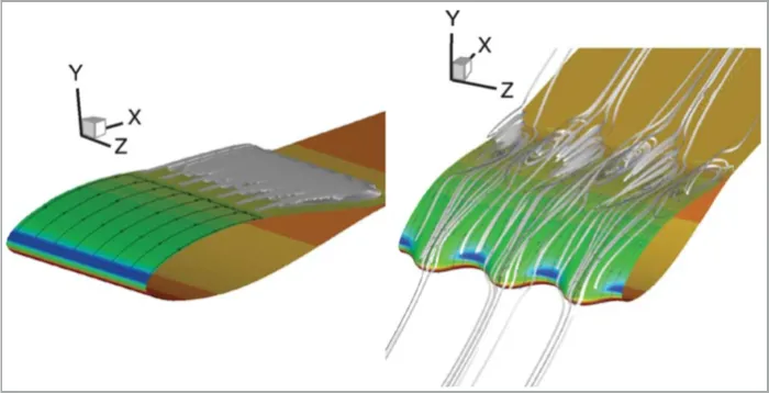
There is also a development in the compressor blades that draws inspiration from humpback whales! The compressor blades, just like the flippers of humpback whales, are miniature aircraft wings. Aircraft wings are susceptible to stall- a condition where the flow of fluid ceases to adhere to the wings, thus reducing the ability of the wings to manipulate the airflow. In whales, their flippers stalling will make them work harder to swim. In compressors, stalling causes a decrease of the pressure in the combustion chamber. Humpback whales, through the magic of evolution have acquired tiny structures called ‘tubercles’ on their flippers which, like micro vortex generators, disturb the flow of water, increasing its ability to adhere to the flipper. Jatayu has similar tubercles on its compressor blades, which delays the onset of stall in its compressor by ‘disturbing’ the flow of air over it. By incorporating this, the team made the engine safer and expanded its operating range.
The Combustion Chamber
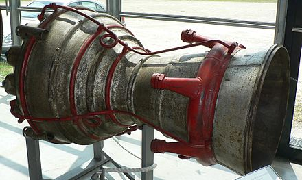
The combustion chamber of the jet engine is where all the action happens. Here, an atomised stream of fuel is injected into the compressed air and ignited. It is this part that is predominantly responsible for thrust production.
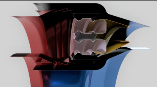
Inside the chamber, a series of scoops are used to guide the air into the combustion zone. The team chose to implement a ‘double annular’ combustion chamber- one which has two inlets into the combustion zone. They accomplished a decrease in the length of the chamber, using this method.
With the continuous burning of air under high pressure occurring in the chamber, cooling is an obvious problem that must be overcome. The team accomplishes this using the bypass air of the engine. The bypass air is air that flows between the combustion chamber and the outer skin of the engine. This air is circulated through the combustion chamber to ensure that its temperature does not exceed 1500K.
The Turbines
After leaving the cumbustion chamber, the hot, fast moving air is made to strike and rotate a series of turbine blades. But why, I hear you ask, do you take away energy from the fast moving air, when that energy can be used to propel the aircraft? The turbine is connected by means of a shaft to the compressor blades. The compressor blades get their energy to rotate from the air that strikes the turbine.
With hot, burning air exiting the combustion chamber, the turbines that it strike have to be kept from suffering structural damage from the high temperatures. The team did so by deciding to use ceramic composites for the blades which can withstand high temperatures. This also eliminated the need for advanced cooling systems of the turbines.
The Exhaust Nozzle
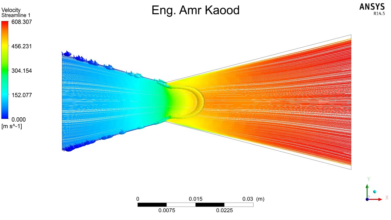
The exhaust nozzle is the part of the engine through which the air finally leaves. The team opted to use a convergent- divergent nozzle- one with an unsymmetric hourglass shape. Keep in mind that the hot gases exiting the turbine are travelling at a speed less than that of sound. The nozzle is designed such that when the gases reach the ‘throat’, they travel at the speed of sound or slightly faster than it. The converging section of the nozzle speeds up the flow of air much like how partially closing a garden hose causes the water to emerge from it at a greater speed.
The ‘throat’ of the nozzle has the highest pressure of air anywhere in the nozzle. as ensured by the divergent section. This prevents shock waves that form from the gases that go supersonic from travelling back into the engine. This is how the team ensured that the nozzle produces the maximum amount of thrust without compromising the performance of the engine.
Conclusion
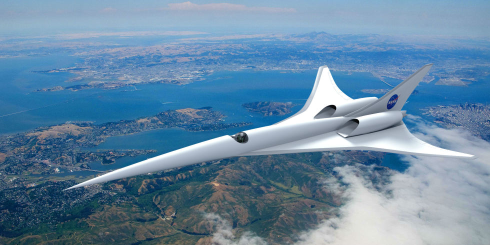
With the efforts of organisations like NASA, companies like Aerion, Boom Supersonic and Boeing and that of bright minds like Aero Sapiens, a future where supersonic flight is not restricted to just military aircraft could be well within reach! There are however, numerous engineering challenges as hurdles- designing a machine that travels faster than the speed of sound is obviously not an easy task! The twenty years that some of the smartest aerospace engineers took to develop the Concorde is testament to this fact. But as seen from history, there is seldom a hurdle that cannot be overcome by clever thinking. It surely will not be long before sleek, yet powerful beasts sporting ramp inlets to show off their supersonic capability, pull over at your local airport to take you to your destinations at unprecedented speeds!